


Views: 0 Author: Site Editor Publish Time: 2026-10-20 Origin: Site


Are strict deadlines and soaring labor costs threatening your tunnel project margins? Picture the damp, confined space of a newly excavated utility tunnel. Traditional formwork setup involves manual bolting, heavy bracing, and tedious alignment. This grueling process easily consumes an entire shift. Such outdated methods are agonizingly slow. They also demand heavy manual labor. This drastically increases the risk of structural alignment errors. The result? Costly, time-consuming rework.
In this comprehensive guide, you will discover how upgrading to an advanced lining system fundamentally transforms concrete pouring efficiency. It safeguards your crew. Most importantly, it protects your bottom line.
Unmatched Efficiency: Advanced lining systems significantly reduce operational cycle times in tunnel concrete pouring through integrated hydraulic automation and motorized walking systems.
Structural Superiority: The central longitudinal design provides exceptional stability and load-bearing capacity. This makes it the standard choice for full-section lining in hydraulic, utility, and subway tunnels.
Cost-Effective Operation: By minimizing the reliance on manual labor crews and reducing material waste, these engineered trolleys offer a measurable and rapid return on investment.
Customizable Solutions: Modern formwork trolleys are tailored to specific tunnel cross-sections. They easily accommodate varying geometric layouts, tight turning radii, and complex geological conditions.
Global infrastructure demands are surging. Urban centers desperately need intricate utility corridors and subway networks. Consequently, the underground construction sector is experiencing a massive technological shift. Market analyses reveal a definitive move away from traditional manual formwork. Contractors now favor automated, smart lining solutions.
Why the sudden change? Increasingly stringent safety regulations play a massive role. The shrinking pool of skilled manual labor is another critical factor. Investing in modernized, hydraulically driven equipment is no longer just a luxury. It is a strict baseline requirement for winning competitive civil engineering bids. Project owners demand flawless concrete finishes and accelerated timelines, forcing construction firms to adopt equipment that guarantees precision without the massive headcount.
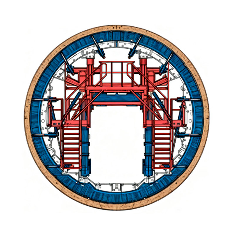
Achieving a precise, durable, and waterproof concrete finish is critical in modern underground construction. The Needle Beam Lining Trolley serves as a specialized piece of heavy equipment engineered explicitly for secondary concrete lining. Temporary wooden formwork or hand-assembled modular steel plates are prone to shifting. In contrast, this machinery operates as a cohesive, mobile system. It moves sequentially through the excavated tunnel, facilitating continuous, high-quality concrete placement.
The defining characteristic of this equipment lies in its core structural difference from traditional gantry systems. At the heart of the machine is a heavy-duty central longitudinal beam. Engineers commonly refer to this as the needle beam. This robust central axis acts as the primary support structure for the entire formwork assembly.
Because the central beam bears the immense load and facilitates movement, the trolley does not require a complex, space-consuming lower portal frame. This lack of lower obstruction allows the equipment to operate efficiently in highly confined spaces. It supports the formwork panels from the center outward. The needle beam essentially acts as a highly stable spine. This enables the machine to inch forward along the tunnel axis while maintaining strict geometric tolerances.
The operational cycle follows a strictly controlled mechanical sequence. This sequence optimizes both structural integrity and site safety. First, operators maneuver the trolley into the designated section. The self-propelled mechanism aligns the central axis perfectly with the tunnel trajectory. Next, integrated hydraulic cylinders extend outward from the central beam. These cylinders push the heavy steel formwork panels into precise position against the excavated rock profile.
Once the formwork is rigidly secured, concrete is pumped into the annular space between the steel templates and the rock face. The full-section design allows for an uninterrupted, 360-degree pour. The formwork remains locked in place under hydraulic pressure while the concrete undergoes its initial curing phase. This guarantees a flawless surface finish. Finally, after the concrete achieves the required compressive strength, the hydraulic cylinders retract the panels. The trolley then uses the needle beam as a track to propel itself forward, ready to repeat the cycle.
For engineering procurement managers and project directors, the primary metric of any formwork equipment is its impact on the critical path of the project schedule. Understanding why this equipment fundamentally alters project timelines requires a closer examination of its operational mechanics.
Manual formwork adjustments can take days. Advanced trolleys replace these tedious manual adjustments with centralized hydraulic automation. A sophisticated network of high-pressure hydraulic cylinders controls the expansion, retraction, and micro-adjustment of the steel templates.
Operators manage this entire process via a centralized control panel. This automation allows for the rapid setting and stripping of the formwork. It frequently reduces transition times from several days to mere hours. Furthermore, hydraulic safety locks maintain consistent pressure during the pour. This completely eliminates the risk of formwork shifting and subsequent alignment errors.
One of the most critical structural challenges in tunnel construction is the formation of weak points known as cold joints. These occur when fresh concrete is poured against partially set concrete. Cold joints are highly susceptible to water ingress. This represents a catastrophic failure for hydraulic and subway tunnels.
Specifically, the structural integrity of the central beam allows the equipment to support the immense hydrostatic pressure of wet concrete across a full cross-section. Contractors can pour the floor invert, sidewalls, and crown arch simultaneously. This eliminates longitudinal construction joints entirely. This continuous pouring capability accelerates the production schedule. It also results in a structurally superior, naturally waterproof tunnel lining.
Labor costs and site safety are persistent challenges in underground engineering. Deploying a customized tunnel formwork trolley fundamentally shifts the labor dynamic on site. The travel mechanism is motorized and the alignment is hydraulically controlled. Consequently, the need for large scaffolding crews and manual formwork carpenters is virtually eliminated.
A standard operation typically requires only a small team of trained technicians. They oversee the hydraulic controls, monitor the concrete pumping, and manage the forward progression. This drastic reduction in manual labor lowers daily operational expenditures. It also significantly mitigates the risk of workplace injuries associated with heavy lifting and working at heights.
Evaluating tunnel formwork requires a deep dive into the material science and structural engineering that dictate performance. Procurement decisions must rely on objective technical specifications rather than surface-level features.
The needle beam is the critical load-bearing component. It must withstand the immense bending moments and torsional forces exerted during both the concrete pouring phase and the travel phase. Manufacturers typically utilize high-grade structural steel, such as Q345 or Q355. These grades offer high yield strength and excellent welding properties. Additionally, engineers validate the beam using Finite Element Analysis. This ensures deflection remains strictly restricted to less than 3mm under maximum load, preventing any distortion in the final concrete profile.
The quality of the final concrete finish is directly proportional to the quality of the steel templates. The face plates are generally constructed from 8mm to 12mm thick carbon steel. This thickness provides the necessary rigidity to resist concrete pressure without bulging. These plates undergo precise machining and polishing to ensure a frictionless surface. A smooth surface is vital for achieving a defect-free concrete finish that meets stringent hydrodynamic flow requirements.
Modern advancements have transformed the control mechanisms of these trolleys. Advanced proportional valves allow for millimeter-accurate positioning of the formwork. Multiple hydraulic cylinders are electronically synchronized through a Programmable Logic Controller. This ensures that the formwork expands and retracts uniformly, preventing mechanical binding. High-capacity hydraulic pump stations, operating between 16 MPa and 25 MPa, provide consistent, reliable pressure throughout the duration of the pour.
Component | Typical Specification or Material | Engineering Function |
|---|---|---|
Needle Beam | Q345 or Q355 Structural Steel | Primary load-bearing axis, prevents deflection, facilitates movement. |
Formwork Panels | 8mm to 12mm Machined Steel | Resists hydrostatic concrete pressure; ensures smooth finish. |
Hydraulic Cylinders | High-pressure, double-acting | Expands and retracts formwork; provides micro-adjustment. |
Control System | Programmable Logic Controller synchronization | Ensures uniform movement; enhances operator safety. |
Walking Mechanism | Electric motor with planetary gear | Enables self-propelled forward movement along the tunnel axis. |
Selecting the correct formwork system requires matching the equipment to the specific geometric and logistical constraints of the site. While both systems are viable, they serve distinctly different engineering environments.
Traditional portal trolleys, also known as gantry trolleys, feature a large A-frame or box-frame structure that rests on rails laid on the tunnel invert. This lower framework consumes significant internal space. In stark contrast, needle beam systems operate from a central suspended axis. They take up far less internal volume. This makes a motorized needle beam trolley the optimal choice for tunnels with smaller cross-sections, typically under 8 meters in diameter, where a portal frame would severely restrict ventilation and equipment passage.
Portal trolleys require the prior installation of heavy steel rails along the tunnel floor. This is a time-consuming process that must precede the formwork operation. Conversely, equipment with advanced self-walking mechanisms utilizes the completed invert or the central beam itself as the track. This streamlined design drastically reduces setup time. It allows for a much faster transition between pouring cycles.
The industry is rapidly abandoning traditional methods in favor of smart, automated solutions. Modernized equipment is packed with features designed to solve real-world engineering headaches.
Standardized equipment rarely meets the complex geological demands of modern underground projects. Today, reputable manufacturers utilize advanced 3D modeling software during the design phase. By simulating the exact geometry of the tunnel cross-section, engineers can identify potential spatial conflicts before manufacturing begins. This digital-first approach ensures that the steel formwork panels align perfectly with the required tunnel radius. It also allows for the precise integration of concrete pouring windows and inspection walkways.
Safety remains the paramount concern. Recent iterations of lining equipment have shifted away from purely manual oversight to automated, fail-safe mechanisms. Modern systems incorporate hydraulic locking valves. These valves maintain pressure even in the event of a sudden power failure or hose rupture, preventing the formwork from collapsing.
Additionally, mechanical anti-fall devices and heavy-duty safety pins are integrated into the support structures. Overload protection sensors continuously monitor the stress on the hydraulic cylinders. If the pressure exceeds safe operational thresholds, the system automatically halts. This mitigates the risk of structural damage or operator injury.
Historically, moving heavy formwork required external towing equipment like winches or locomotives. This added logistical complexity and safety hazards to the confined tunnel environment. Contemporary designs feature self-propelled walking systems driven by integrated electric motors and gear reducers. Utilizing Variable Frequency Drives, operators can precisely control the travel speed. This ensures highly accurate positioning for the next pouring cycle.
The structural characteristics of this equipment make it highly adaptable to specific types of underground infrastructure. The central-beam design excels in environments where space is limited and full-section structural integrity is non-negotiable.
In hydraulic engineering, the concrete lining must withstand immense internal and external hydrostatic pressure while minimizing friction for water flow. This system is particularly effective here because it facilitates full-section pouring. By casting the invert, sidewalls, and crown simultaneously, contractors avoid creating weak joints. These joints are traditionally the most common sites for high-pressure water leaks.
Urban underground transit systems often require navigating tight spatial constraints. The absence of a bulky lower portal frame means that the central area beneath the beam remains relatively unobstructed. This spatial efficiency is crucial for maintaining proper ventilation and providing safe evacuation routes for personnel.
Procuring heavy underground construction equipment represents a significant capital expenditure. The reliability of the formwork directly impacts project profitability. Therefore, evaluating potential suppliers requires a rigorous, evidence-based approach.
A manufacturer's track record is the most reliable indicator of product quality. Procurement managers should look for suppliers who provide detailed material traceability reports. Verify that the steel grade used for the main beam meets Q345 or Q355 standards. Subpar steel will deform under the weight of wet concrete, leading to disastrous alignment issues. Partnering with established industry entities ensures the equipment has been rigorously tested.
No two underground projects share identical specifications. A competent manufacturer must function as an engineering partner rather than a mere vendor. They should possess the in-house engineering capacity to analyze your specific turning radii and concrete pouring sequences. Ultimately, they must deliver a bespoke Needle Beam Lining Trolley that accommodates your exact requirements. This includes modifying hydraulic cylinder layouts and integrating specialized vibration systems tailored to your concrete mix.
The complexity of assembling and calibrating hydraulic and electrical systems on-site requires professional oversight. Decision-makers must verify that the manufacturer offers comprehensive after-sales support. This should include the dispatch of technical personnel for on-site assembly guidance, hands-on operational training for the local workforce, and a guaranteed supply chain for critical replacement parts like hydraulic seals.
Upgrading your tunnel construction equipment is one of the most effective ways to improve project speed and site safety. An advanced lining system ensures precise structural results, completely eliminating the inconsistencies associated with manual timber or modular steel forms. This level of precision helps contractors meet strict project deadlines while avoiding the crippling financial penalties of rework.
Ultimately, investing in reliable, automated formwork secures long-term profitability. By making careful equipment selections, construction firms can drastically reduce costly manual labor requirements. If you are preparing for an upcoming underground project, do not let outdated equipment drain your budget. Explore the high-performance solutions at JC Formwork to find the perfect automated formwork system tailored to your specific site conditions.
These systems are highly customizable but are exceptionally well-suited for small to medium cross-section tunnels. Typically, they are deployed in tunnels ranging from 3 meters to 10 meters in diameter. Because the design does not rely on a wide portal frame, it is the standard choice for narrow hydraulic, diversion, and utility tunnels where internal spatial constraints make traditional gantry equipment unviable.
Hydraulic automation fundamentally reduces the need for manual intervention in hazardous zones. The system utilizes synchronized hydraulic cylinders to expand and retract the heavy steel formwork panels. Operators control this process from a centralized, safe location, eliminating the need for workers to manually maneuver heavy steel plates. Furthermore, modern hydraulic systems incorporate safety lock valves that hold the formwork rigidly in place, preventing accidental collapse even if hydraulic pressure is unexpectedly lost.
Yes, they can be engineered to accommodate specific turning radii. For projects with curved alignments, manufacturers design the trolley with articulated joints along the central beam and adjustable overlapping formwork panels. This modular flexibility allows the equipment to smoothly navigate curves without compromising the structural integrity of the concrete lining or causing binding against the excavated rock face.
Assembly timelines depend on the specific dimensions and complexity of the equipment. However, it generally takes between two to four weeks. Reputable manufacturers utilize modular design principles and precision-machined flanged connections to expedite this process. To ensure safety and operational accuracy, it is highly recommended that the manufacturer's technical representatives oversee the initial on-site assembly, hydraulic calibration, and the first test pour.
Full-section lining involves pouring the concrete for the entire circumference of the tunnel in a single, continuous operation. Needle beam trolleys are renowned for facilitating this highly efficient method. Partial-section lining separates the process, usually pouring the bottom invert first, followed by the arch later. Full-section lining is structurally superior because it eliminates longitudinal construction joints, significantly enhancing the tunnel waterproofing capabilities and overall load-bearing strength.
When manufactured with high-grade 8mm to 12mm carbon steel and properly maintained, the formwork panels can withstand hundreds of pouring cycles. Regular cleaning, application of quality form release agents, and prompt repair of any surface abrasions will significantly extend the operational lifespan of the steel templates across multiple projects.
Routine maintenance is critical for hydraulic reliability. Site engineers should conduct daily inspections of hydraulic hoses for signs of wear or leakage. It is essential to monitor hydraulic fluid levels and maintain system pressure between the recommended 16 MPa and 25 MPa. Additionally, hydraulic filters should be replaced according to the manufacturer schedule to prevent particulate contamination from damaging the proportional valves or pump station.


