


Views: 0 Author: Site Editor Publish Time: 2026-10-20 Origin: Site


Spanning deep valleys, active highways, or unpredictable rivers presents unique logistical nightmares. Traditional ground scaffolding fails here. It becomes physically impossible or financially ruinous. We need a different approach. Enter the Cantilever Bridge Construction Machine. Out in the field, we usually just call it a form traveler. This equipment is the absolute backbone of the balanced cantilever construction method. It lets crews cast massive concrete segments mid-air. The accuracy? Down to the millimeter.
This guide serves as a practical blueprint for project managers, procurement officers, and civil engineers. We will break down the mechanics of these machines and dissect the various types available. We will also outline non-negotiable safety rules and provide a concrete framework for selecting the right equipment for your next high-altitude project.
These machines eliminate the need for ground-supported falsework. They are the industry standard for high-altitude and deep-water infrastructure.
Choosing between overhead and underslung designs dictates how you manage bridge geometry and strict clearance limits.
Safety relies on symmetrical pouring sequences and real-time hydraulic monitoring to prevent catastrophic imbalances.
Equipment selection requires hard data. You must analyze maximum dynamic load capacity, horizontal curvature, and cycle times.
Daily maintenance and post-pour inspections extend the lifespan of structural steel and keep crews safe.
A form traveler is a highly engineered, movable steel framework. Field crews use it primarily to build large-span concrete box girder bridges. It acts as a mobile support system. This allows teams to cast concrete segments in place, advancing outward from a central pier in perfect symmetry.
The entire philosophy behind this equipment is equilibrium. The machine supports the immense dead weight of wet concrete, dense steel rebar, and active personnel. It holds this load securely until the newly poured segment cures and gains compressive strength. Once crews secure the post-tensioning cables, the segment becomes structurally independent. The machine then uses a synchronized hydraulic system to glide forward to the next section.
Selecting the right structural variation impacts load distribution and daily site efficiency. The equipment generally falls into three categories. Each is engineered to solve specific logistical hurdles.
Overhead form travelers are the workhorses of standard box girder bridge construction. The primary load-bearing steel trusses sit directly above the bridge deck. High-strength steel tension rods suspend the formwork—the molds shaping the concrete—from these overhead trusses.
This top-heavy design delivers massive load-bearing capacity. It is the go-to choice when overhead space is unrestricted. Heavy lifting cranes and trusses can operate freely above the working surface.
Conversely, underslung form travelers position their primary structural support beneath the deck. A robust steel undercarriage supports the molds from below instead of hanging them from above.
Engineers specify underslung models when facing severe overhead clearance limits. Building beneath existing high-voltage lines or multi-tier urban overpasses demands this lower profile. Furthermore, this is the standard choice for cable-stayed bridges. Overhead trusses would physically block the installation of diagonal stay cables.
Form travelers handle wet, cast-in-place concrete. Launching gantries serve a different function. Instead of pouring concrete hundreds of feet in the air, a gantry lifts and aligns pre-cast segments manufactured off-site.
The gantry acts as a mechanical bridge. It holds heavy precast segments perfectly still while crews secure them with post-tensioning tendons and high-strength epoxy. This method drastically cuts down the construction timeline.
Equipment Type | Primary Application | Clearance Requirement | Typical Load Capacity |
|---|---|---|---|
Overhead Form Traveler | Standard cast-in-place box girder bridges | Requires unrestricted overhead space | 150t to 400t+ per segment |
Underslung Form Traveler | Cable-stayed bridges, areas with height limits | Requires low overhead profile | 100t to 300t per segment |
Launching Gantry | Precast segmental bridge construction | Requires massive pier support capacity | Up to 1000t+ (precast blocks) |
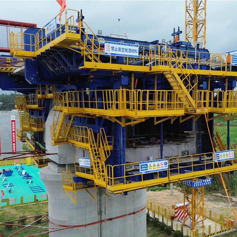
The reliability of a custom cantilever bridge construction machine depends on seamlessly integrating several subsystems. Knowing how these parts interact is vital for maintenance and safety.
Main Truss System: We fabricate this backbone from high-yield structural steel, typically Q345 or Q460 grades. It absorbs the dead load of the concrete and the dynamic vibrations from concrete vibrators. It safely transfers these forces back into the mature sections of the bridge.
Anchoring and Suspension System: This linkage keeps the machine bolted to the deck. High-tensile anchor rods secure the rear of the traveler to hardened concrete. This counteracts the massive tipping forces generated when the front fills with fresh concrete.
Hydraulic Advancing System: Modern travelers rely on synchronized hydraulic cylinders. Once a segment cures, these cylinders push the structure along heavy-duty rails equipped with PTFE sliding bearings. This prevents sudden jolts that could misalign the formwork.
Formwork System: Comprising inner, outer, and bottom molds, this dictates the bridge's geometric precision. We design advanced panels with quick-release mechanisms. This allows crews to adapt rapidly to changes in web thickness or floor curvature.
Infrastructure demands are changing. We need bridges built faster and stronger. This urgency drives massive shifts in construction technology. Purely mechanical systems are becoming obsolete. Today, the trend leans heavily into data-driven, automated solutions.
Modern form travelers now integrate smart sensors. These devices monitor stress-strain ratios and hydraulic cylinder pressures in real time. If an asymmetric load occurs during a pour, the system alerts ground control instantly. In addition, manufacturers are utilizing lightweight, ultra-high-strength alloys. This reduces the machine's self-weight, lowering transportation costs and carbon footprints. The future of high-altitude construction relies on digital precision just as much as brute strength.
Wind howling at 150 meters up changes everything. Equipment reliability is survival. Operating heavy machinery at extreme elevations requires an uncompromising approach to risk management.
Rigorous Load Testing: Before pouring a single drop of concrete, the assembled equipment undergoes exhaustive load testing. Site engineers simulate the heaviest expected segment using water tanks or steel ingots. This verifies welded joints, measures downward deflection, and proves the rear anchoring system holds under maximum stress.
Environmental Monitoring: Weather dictates the schedule. Safety officers enforce strict thresholds. Lifting operations and hydraulic advancements halt immediately if wind speeds exceed Grade 6 levels, roughly 10.8 to 13.8 meters per second. Temperature drops also delay concrete curing, forcing the machine to bear the load longer.
Symmetrical Pouring: Equilibrium is everything. Pump trucks must deliver concrete symmetrically to both sides of the pier. If one side receives significantly more wet concrete, the unbalanced moment force can twist or fracture the pier. We enforce synchronized pumping schedules strictly.
Worker Fall Protection: Crews navigate narrow walkways suspended at dizzying heights. The machine must feature rigid toe-boarded guardrails and non-slip steel grating. Designated tie-off anchor points for fall arrest harnesses are mandatory.
The global adoption of this technology comes down to hard economic and logistical facts.
Cost and Time Efficiency: You eliminate ground scaffolding entirely. Building temporary steel falsework from a valley floor up to a 100-meter deck is financially ruinous. Form travelers bypass this, slashing material costs and speeding up the project.
Environmental Protection: Construction happens top-down. The ecosystem below remains untouched. This makes the cantilever method perfect for spanning protected wetlands, deep gorges, or active urban transit corridors without blocking ground traffic.
Structural Adaptability: These machines handle complex geometries. Through precise mechanical adjustments, engineers manage varying span lengths, tight horizontal curves, and steep longitudinal gradients seamlessly.
Selecting equipment means moving beyond basic brochures. You need a rigorous evaluation of the machine against your specific bridge design. Here are the actionable standards.
Assess Dynamic Load Capacity: Look at the heaviest segment closest to the pier. A standard robust traveler should comfortably handle segment weights ranging from 150 to over 400 tons. You must also factor in dynamic loads like wind pressure and machinery vibration. Always demand a built-in safety factor.
Evaluate Bridge Geometry Parameters: Bridges are rarely straight and flat. Your equipment must navigate specific turning radii—often requiring capabilities for curves as tight as R≥150m. If your box girder features a variable cross-section, the formwork must expand and contract smoothly to match changing dimensions.
Target Cycle Time Efficiency: Profitability ties directly to cycle times. Procuring a system with automated hydraulics and quick-release formwork can reduce a standard 7-day pouring cycle down to 5 days. Over a 50-segment bridge, that efficiency saves months of labor.
Demand Manufacturer Engineering Support: Bridge-building equipment is not off-the-shelf. Partnering with a reliable manufacturer ensures you get accurate structural calculations and on-site assembly supervision. Rapid technical support is vital when troubleshooting field challenges.
Structural fatigue is inevitable in harsh environments. Proactive maintenance preserves safety and keeps the project moving.
Daily Pre-Operation Checks: Before every shift, engineers conduct visual inspections. They check hydraulic hoses for micro-leaks. They verify the torque on primary anchor bolts. They inspect structural pins for metal fatigue. Documenting this in a logbook is mandatory.
Post-Pour Maintenance: Wet concrete is highly alkaline and corrosive. After a pour and advancement, laborers must scrape splatter from the steel formwork before it hardens. Applying high-quality release agents to cleaned panels prevents future buildup. This guarantees a smooth finish on the next segment.
Storage and Disassembly: The closure pour connects the two advancing cantilevers. Once post-tensioned, the bridge becomes continuous. Disassembling the travelers requires strict reverse-engineering protocols. Crews use heavy cranes to lower steel components safely. Proper cleaning of hydraulic parts ensures the equipment is ready for the next job.
A high-quality cantilever bridge building equipment setup is the lifeblood of large-span infrastructure. It provides unmatched structural support, slashes construction time, and protects the environment below.
However, the sheer power of this machinery demands an unwavering commitment to safety. Proper equipment selection, rigorous load testing, and daily maintenance prevent accidents and guarantee project success.
If you are managing a complex bridge project, do not guess on your equipment specs. Evaluate your load capacities, curve radii, and cycle time goals. Reach out to the engineering team at JC Formwork to configure a custom form traveler system built specifically for your bridge geometry.
The machine casts individual segments ranging from 3 to 5 meters in length. However, the total bridge span depends on pier design and post-tensioning engineering. Bridges built using this method routinely achieve clear spans exceeding 200 to 300 meters. The machine's limit is the maximum segment weight, not the final bridge length.
Initial assembly takes between 1 to 2 weeks per pair. This depends on crew experience and pier accessibility. Crews assemble main trusses on the ground, lift them to the pier's zero-segment, install hydraulics, and conduct mandatory load testing before any movement begins.
Yes. Customization is mandatory. Every bridge has unique structural parameters. Manufacturers engineer the load-bearing trusses, formwork curvature, and hydraulic leveling systems to match your exact cross-section, turning radius, and longitudinal gradient.
Engineers execute a closure pour. They cast a specialized, slightly shorter segment to connect the two independent cantilevers. Crews do this during the coolest part of the day to limit thermal expansion. Once cured and stressed, the bridge becomes a stable continuous span, and the machines are dismantled.
Safety factors are non-negotiable in high-altitude engineering. Most international standards require a minimum safety factor of 1.5 for the main structural steel components. The anchoring and suspension systems often demand an even higher factor, typically around 2.0. This ensures the equipment withstands unexpected dynamic loads like sudden wind gusts.
Weather dictates the pace of the entire project. High winds can halt hydraulic advancement completely. Extreme cold slows down concrete hydration, meaning the equipment must bear the dead load for extra days before post-tensioning can occur. Conversely, extreme heat requires pouring at night to prevent the concrete from curing too quickly and cracking.


